Shakti “E Class” has 1 Inter Integrated Circuit (I2C) with 128kB RAM. In this tutorial, we are going to discuss the process to access real- time clock (RTC) using I2C communication protocol with Arduino IDE.
What is I2C?
I2C (Inter-Integrated Circuit) pronounced I-squared-C or I-two-C, is a synchronous, multi-master, multi-slave, packet switched, single-ended, serial communication bus invented in 1982 by Philips Semiconductor (now NXP Semiconductors). It is widely used for attaching lower-speed peripheral ICs to processors and micro controllers in short-distance, intra-board communication.
HOW I2C works?:
I2C combines the best features of SPI and UART protocol. With I2C, you can connect multiple slaves to a single master (like SPI) and you can have multiple masters controlling single, or multiple slaves. This is really useful when you want to have more than one micro controller logging data to a single memory card or displaying text to a single LCD.
Like UART communication, I2C only uses two wires to transmit data between devices,
- SDA (Serial Data) – The line for the master and slave to send and receive data.
- SCL (Serial Clock) – The line that carries the clock signal.


I2C is a serial communication protocol, so data is transferred bit by bit along a single wire (the SDA line). Like SPI, I2C is synchronous, so the output of bits is synchronized to the sampling of bits by a clock signal shared between the master and the slave. Also, the clock signal is always controlled by the master.
I2C-Data-Frame:

What is Real Time Clock (RTC)?
A real-time clock (RTC) is an electronic device (most often in the form of an integrated circuit) that measures the passage of time. Although the term often refers to the devices in personal computers, servers and embedded systems, RTCs are present in almost any electronic device which needs to keep accurate time.
In this tutorial we are going to use the DS3231 module. The DS3231 RTC module Precise Real-Time Clock Module is a low-cost, extremely accurate I²C real-time clock (RTC) with an integrated temperature-compensated crystal oscillator (TCXO) and crystal. The device incorporates a battery input and maintains accurate timekeeping when the main power to the device is interrupted.
Also check out this article DS3231 on Shakti Processor.
What will you need?
- Arty7 35t/100t board with either
pinaka, parashu or vajraprogrammed. - DS3231 RTC module
- Jumper Wires
- Installed SHAKTI supported boards in Arduino IDE.
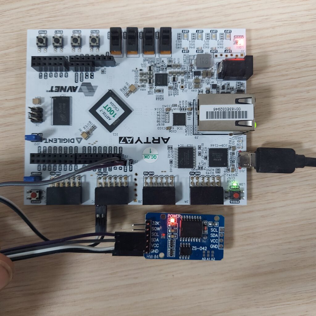
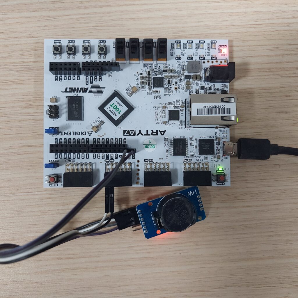
Circuit diagram
Connect Arty and DS3231 according to the below diagram,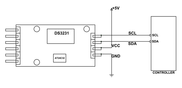
LET’S START,
Step 1: Install Arduino IDE
- Firstly, download and install
Arduino IDE 1.8.9 or the latestversion tarball from the Arduino website. - Then unpack it and run the installation script as directed.
Step 2: Install SHAKTI supported boards in IDE
- Add the link below to the
Additional Boards Manager URLsin theFiles->Preferences->Settings.
https://gitlab.com/shaktiproject/software/shakti-arduino-ide/-/raw/master/package_shakti_index.json
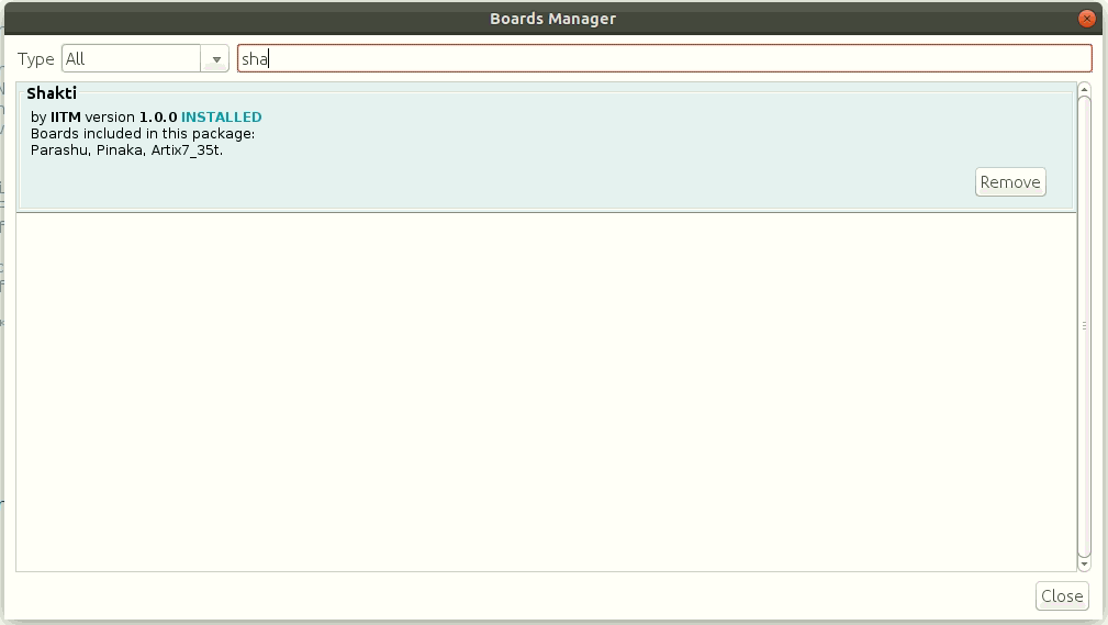
- Then, open the Board Manager Dialog Box,
Tools->Board: -> Select Board Manager
- In the Boards Manager Dialog Box, search the list and install SHAKTI boards.
Step 3: Setting up Arduino IDE for SHAKTI
As we have installed the SHAKTI successfully, we can now proceed with setting up the IDE.
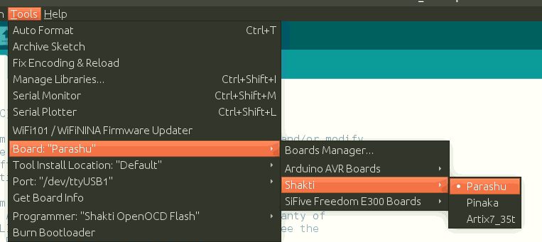
Step 3.1: Firstly, Go to Tools->Board:->Shakti. Then select the board you are going to use.
For instance, we use parashu here.
Step 3.2: Then, Go to Tools -> Port and select the port.
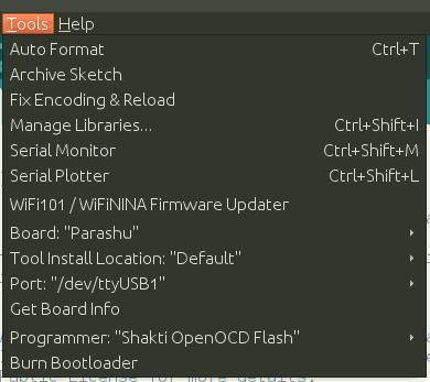
Step 3.3: Lastly, Go to Tools ->Programmer and select Shakti OpenOCD Flash or Shakti OpenOCD RAM based on the need.
- Shakti OpenOCD Flash – This option is used to upload the program to your flash memory. The program will be executed every time the board is reset.
- Shakti OpenOCD RAM – This option is used to upload the program to RAM. The uploaded program would not be retained after a reset.

Step 4: Testing the sketch
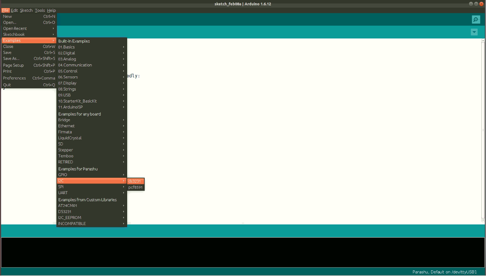
- Firstly, Go to File->Examples->I2C and select ds3231.
- Now, Click on the
Verify icon(Tick icon on top left ) to compile the program.
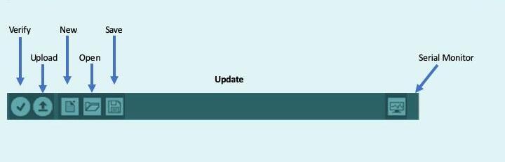
- Then, Click the Upload icon on Arduino IDE (Right arrow key next to verify) to upload the program.
- Finally, switch to the
serial monitorto see if the Program has been uploaded successfully.
Serial Monitor Output:


Mainak is an intern at the RISE labs. He has also interned at the Department of Atomic Energy (UGC-DAE-CSR), Kolkata. His favorite subjects are “Digital Electronics” and “Microprocessor & Micro-controller”. He is also an open source library contributor at Arduino.


Thanks.|