
Shakti is an Open-Source Processor development initiative by the RISE group at IIT Madras, sponsored by MeitY. Being a part of the Swadeshi Microprocessor Challenge and getting the opportunity to work with a SHAKTI Pinaka processor has been quite a journey over the past month. The major challenge was the lack of tutorials to get started with what could possibly be the future of indigenous micro controllers. So if this article helps anyone in starting their journey, that would be great! In this article, we are going to interface a simple 4×4 led matrix and ESP8266 with a pinaka processor. All the codes used in this tutorial can be found in the github repository.
Step 1: Platform IO
The first step was to get any code onto the processor, the 3 options available are,
- shakti-sdk using terminal: I found this quite cumbersome to set up but once done it offers the best features.
- Arduino IDE: From most of the topics on the forums my gut feeling suggested this wouldn’t be a great idea.
- PlatformIO: Balance of option 1 and 2 but the only downside being you can only upload the code onto the RAM at the moment and not the flash memory i.e you have to re-upload the code every time you power it off.
Note: shakti-sdk and shakti-tools are currently a private repository. Please login or sign up to Gitlab and request access here before using it. Also, option 2&3 are available for Windows but I failed to get PlatformIO running on Windows as I could not get the drivers to interface properly.
- The shakti blog is a great step to get started in setting up PlatformIO
These are a few steps that I came across that might be helpful while using PlatformIO
- Every time the board is plugged into the system, read write permissions can be given in the terminal using
sudo chmod a+rw /dev/ttyUSB1
- For seeing the output on the monitor the order of actions followed were,
build > upload > monitor> Run without debugging >monitor
That’s about setting PlatformIO, now onto the coding!!
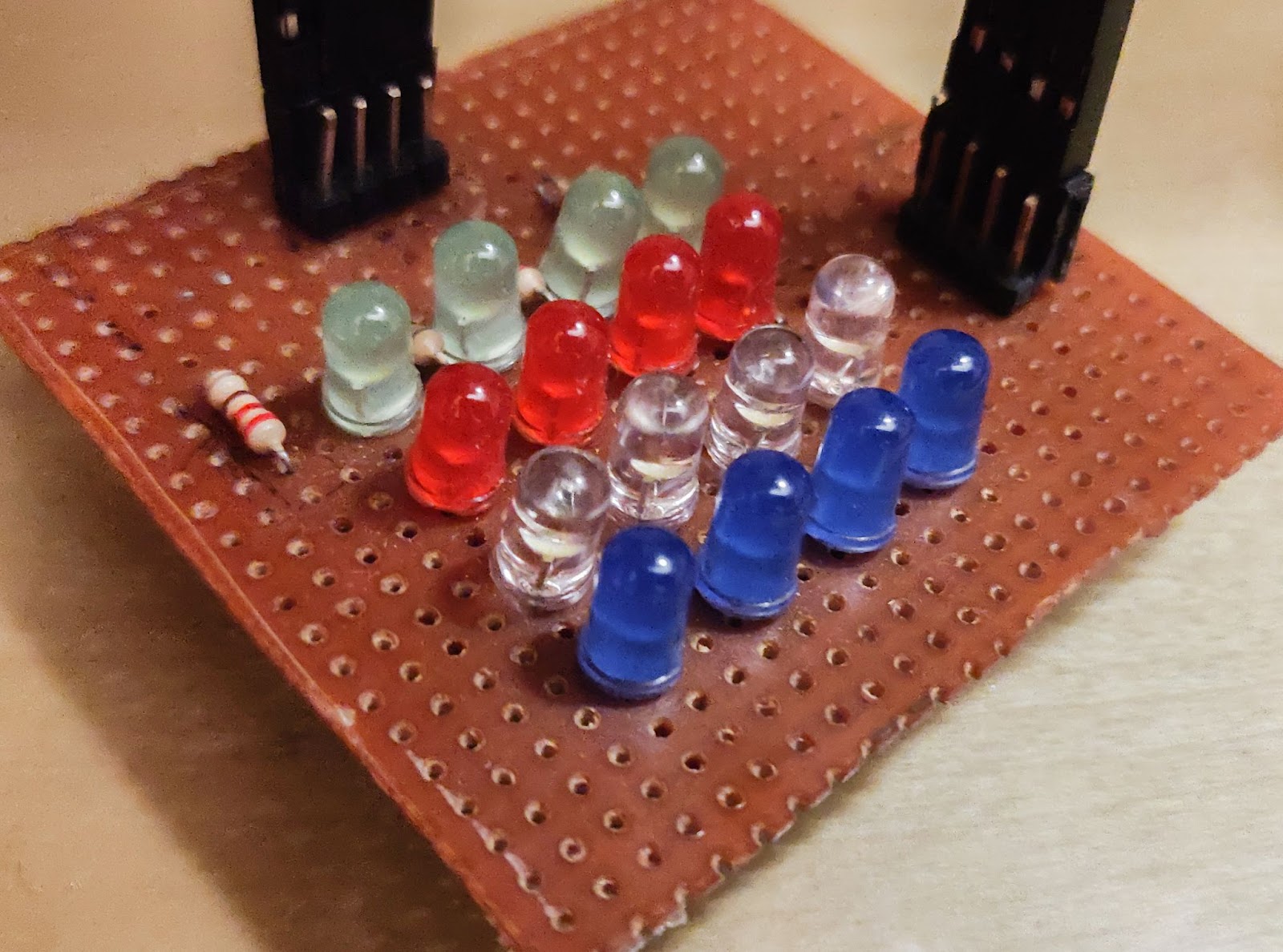
Step 2: Understanding GPIO – 4×4 Matrix
- GPIO 2-5 are used for the cathodes
- GPIO 7-10 are used for anodes
This step helps in understanding how the GPIOs in a Pinaka processor work.
Note: I did not spend much time to actually use the matrix to its full potential. At the moment it can only be set to glow one led at a time.
The two major things to keep in mind,
- write_word(GPIO_DIRECTION_CNTRL_REG, 0x00000FFF); configures a 32 bit register that sets each of the 32 GPIOS’s as an input or output.
- 1 for output
- 0 for input
- GPIO_DATA_REG is a 32 bit register that:
- writes data stored to each register in case of output and
- Stores the data read in case of input.
More details can be found in the GPIO examples in the shakti-sdk
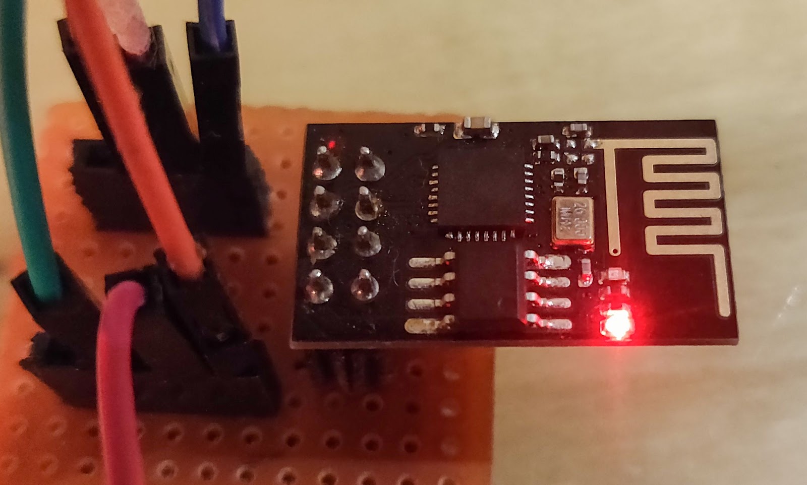
Step 3: ESP8266
Connecting your microcontroller to a WiFi module can open up a lot of possibilities such as IoT applications, home automation, sending sensor data over the WiFi. The ESP8266 is a cheap and reliable solution to achieve the same. The major challenge in interfacing with the ESP8266 was most tutorials online use the Blynk app or a prebuilt library, but overcoming these challenges makes one truly understand how the ESP8266 works.
- The ESP8266 is interfaced using the UART interface available on pins 0 and 1 on the shakti processor
- By sending strings which are termed as AT commands we can configure and control the ESP8266.
- The list of at commands can be found here
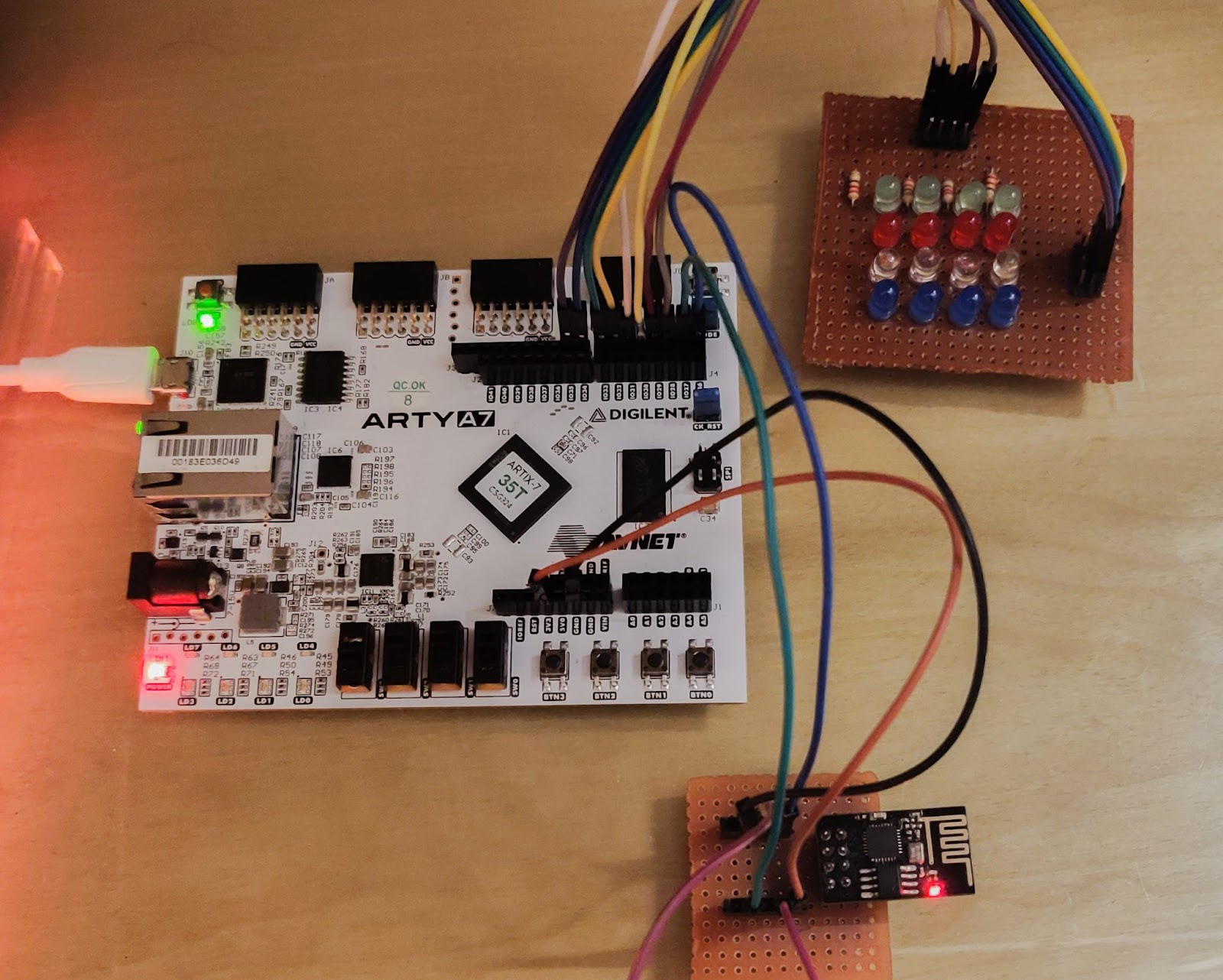
The connections for the board are as follows,
| Esp8266 | Shakti |
| Vcc | 3.3v |
| Gnd | Gnd |
| ch_en | 3.3v |
| Tx | Rx (GPIO-0) |
| Rx | Tx (GPIO-1) |
- The basic way to use the board was understood by the example project provided by IIT-M and served as a base to understand the
uartcommands. - Understanding the webpage functioning and building the code was from this well-documented article here

Step 4: Understanding the Pinmux Design and Data Processing
Pinmux design
This is a crucial concept when interfacing multiple types of peripherals. Few PINS on the board serve multiple purposes. We have to let the microcontroller know what we will be using them as. The pinmux mapping can be found in the user manual.
*pinmux_config_reg = 0x5; //sets the binary value 0101 which allows the GPIO 0 AND GPIO 1 to be used as UART-1 PinsProcessing data sent by the esp8266
- The data sent by the web page can be seen by seeing the network tab under inspect option on a web page
- This is the format it is received by the ESP8266 and needs to be processed to extract meaningful data
- This can be used using functions available in the string.h library

Step 5: Bringing It Together.


Now that most of the basic parts are ready it’s about adapting the code to the application you want.
Note: one issue I faced was at times the code crashes after sending the “AT+CIPSERVER=1,80” in that case you have to restart the code.If anyone finds a solution please mention it in the comments!!!
Conclusion
Thanks for making it this far. This isn’t really a tutorial but more of a compilation of my experience in the past month. I hope you find it useful and helps you in any way and would love to hear about your suggestions and projects.

I am 2nd year B.tech interested in power electronics and embedded systems. Would love to have a conversation about F1 ,tech or even Coffee!


really helpful!