
The Microchip Technology Inc. MCP4921 is 2.7 –5.5V, low-power, 12-Bit Digital-to-Analog Converter (DACs) with optional 2x buffered output and SPI interface.The MCP4921’s are Digital-to-Analog Converters (DACs) that provide high accuracy and low noise performance for industrial applications where calibration or compensation of signals (such as temperature, pressure and humidity) are required.
Main Features:
- 12-bit Resolution.
- Single Channel Voltage Output.
- 2.7V to 5.5V Operation.
- Operating Current 175µA.
- Output Settling Time 4.5 µs
Protocol:
The MCP4921 uses the standard Serial Peripheral Interface (SPI).
Step 1: What You Will Need?
- Arty7 35t/100T board with either
pinaka, parashu or vajraprogrammed on it. - shakti-sdk and shakti-tools installed or Platform IO installed and ready
- MCP4921.
- Micro USB Cable.
- Jumper Wires.
Note: shakti-sdk and shakti-tools are currently a private repository. Please login or sign up to Gitlab and request access here before using it.
Step 2: The Circuit
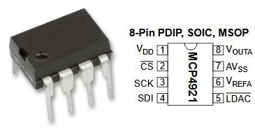
Connections of the MCP4921 sensor:
IC PIN NO 1VDDconnect to 3.3VIC PIN NO 2 CSto SPI CSIC PIN NO 3 SCKconnect to SPI CLKIC PIN NO 4 SDIto SPI MOSIIC PIN NO 5 LDACconnect to GroundIC PIN NO 6 V REFAto VCCIC PIN NO 7 AV SSconnect to GroundIC PIN NO 8 V OUTto Analog DC Output
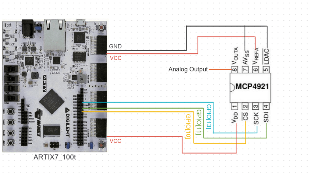
Here we use Arty100t for instance. For better clarity, Check the device pin mapping for pinaka, parashu and vajra.
Step 3: Code
Please click here to have a look at the code.
Code can be compiled and run using the following ways,
- Using terminal on a system with shakti-sdk and shakti-tools installed (Manual method).
- Using Platform IO IDE.
Step 4.1: Manual Method
4.1.1 Compile and build
- Move to
shakti-sdk
cd shakti-sdk
- Compile using
make software PROGRAM=? TARGET=?. Typemake list_applnsto list all the applications available in the SDK. Target can be eitherparashu, pinaka or vajra.
For instance, Use target as parashu,
make software PROGRAM= mcp4921_dac TARGET=parashu
4.1.2 Execution:
Once the application is built, the executable is generated in the output folder. The executable is in ELF file format and they have the extension .shakti. Now, open three terminals, one for each of the following,
- One terminal for UART terminal display
(miniterm) - Another for
GDB server. - And the last one for
OpenOCD.
Terminal 1: Firstly, Connect to serial output by using miniterm or gtkterm with the baud rate of 19200.
For instance,
$ sudo miniterm.py /dev/ttyUSB1 19200
Note:
- “/dev/ttyUSB1” – ttyUSB means “USB serial port adapter”
- The “1” (“0” or “1” or “2”“here means the USB device number on your system. The FPGA board is connected to that USB device number.
Terminal 2: After that, Connect to the FPGA board by using the OpenOCD provided by shakti-tools and its respective configuration file. (Read how OpenOCD and RISC-V GDB work together to establish a connection between our PC and the Microprocessor)
For instance, if we use parashu,
$ cd shakti-sdk
$ cd ./bsp/third_party/parashu
$ sudo $(which openocd) -f ftdi.cfg
For pinaka and vajra, Goto cd ./bsp/third_party/<pinaka or vajra>
Terminal 3: Now, open either 32-bit or 64-bit RISC-V GDB based on your architecture i.e riscv32-unknown-elf-gdb or riscv64-unknown-elf-gdb respectively from shakti-tools.
The output executable is created in <path-to-shakti-sdk>/software/examples/spi_applns/mcp4921_dac/output as mcp4921_dac.shakti.
Load up the .shakti file by following the below steps,
$ riscv32-unknown-elf-gdb
(gdb) set remotetimeout unlimited
(gdb) target remote localhost:3333
(gdb) file path/to/executable
(gdb) load
(gdb) c
4.1.3 Upload to flash
Steps to generate standalone user application:
The SHAKTI-SDK has a uploader tool that is used to load a content (such as ELF) to flash, after building the image.
- Goto the right directory.
cd shakti-sdk
- The make upload command is used to build and upload the application to the flash automatically.
make upload PROGRAM= mcp4921_dac TARGET=parashu
PROGRAM is the new bare metal user application that is created. Type make list_applns to list all the applications available in the SDK.
Step 4.2: Using Platform IO
We can use IDE’s like Platform IO to compile, build, run, upload and debug. Please read the article on Platform IO on SHAKTI to understand the steps.
Miniterm Output:
--- Miniterm on /dev/ttyUSB1: 19200,8,N,1 ---
--- Quit: Ctrl+]  |  Menu: Ctrl+T | Help: Ctrl+T followed by Ctrl+H ---                  ((
                                    ,(((((
                                *((((((
                           ./(((((((
                       ./((((((((
                    *(((((((((
                .(((((((((((
             ,((((((((((((
           ((((((((((((((
          .((((((((((((((
              *(((((((((((
                   /(((((((
                  *((((((((
                     *(((((((
                       (((((((((
                        ((((((((((
                         (((((((((((((
                         ((((((((((((((
                        ((((((((((((
                      *((((((((((
                    (((((((((
              *(((((((
           *((((((
       .(((((
   ./(((
SHAKTI PROCESSORS
Booting… vspi1.0
Booting on Parashu! hart 0
Parashu is a SoC build on top of Artix7 100T.
The core belongs to Shakti E class, 32 bit.
Supported ISA: RV32ACIMNU.
Processor Arch ID: 0.
Device ID 1
extracted device id 2018
. . . . . . .
Control transferred to RAM
Period Register of module number 0 set to 0
Duty Register of module number 0 set to 0
Control Register of module number 0 set to 0
All registers of module number 0 cleared
Period Register of module number 1 set to 0
Duty Register of module number 1 set to 0
Control Register of module number 1 set to 0
All registers of module number 1 cleared
Period Register of module number 2 set to 0
Duty Register of module number 2 set to 0
Control Register of module number 2 set to 0
All registers of module number 2 cleared
Period Register of module number 3 set to 0
Duty Register of module number 3 set to 0
Control Register of module number 3 set to 0
All registers of module number 3 cleared
Period Register of module number 4 set to 0
Duty Register of module number 4 set to 0
Control Register of module number 4 set to 0
All registers of module number 4 cleared
Period Register of module number 5 set to 0
Duty Register of module number 5 set to 0
Control Register of module number 5 set to 0
All registers of module number 5 cleared
All Register values of all modules clearedinit entered
trap_init entered
trap_init exited
SPI init done

 Data value written: 3fff0000Dac Value Written

 Data value written: 3fff0000Dac Value Written - 4096

 Data value written: 30000000Dac Value Written - 0

 Data value written: 3fff0000Dac Value Written - 4096

 Data value written: 30000000Dac Value Written - 0

 Data value written: 3fff0000Dac Value Written - 4096

 Data value written: 30000000Dac Value Written - 0

 Data value written: 3fff0000Dac Value Written - +4096
Akshaya currently works at the RISE labs. Her favorite subjects are Web designing and Microprocessors. She loves learning about new things and writing about them!