
PinMux or Pin Multiplexing is an important concept in embedded systems. By this concept, we can use a single pin for various mutually exclusive functions. These few pins on the board serve multiple purposes and we have to let the microcontroller know what these are. In this article, we are going to see how to configure the pinmux registers for various peripherals.
How to configure PINMUX register?
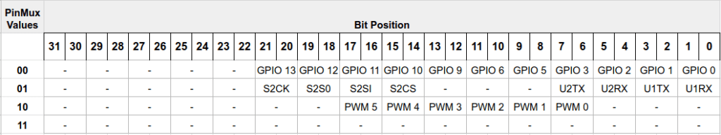
The pinmux configuration register is a 32-bit register located at 0x40310. Two bits of the Pinmux register are allocated to each hardware pin so that a total of 4 (00, 01, 10, 11, also 11 is not used now) operations are possible. The default value of Pinmux Configure Register on reset is 0 (all pins are configured as GPIO).
Following are the pins and their corresponding peripheral mapping. We can enable each peripheral by entering the right values to the pinmux register.
| Pin | Default [00] | Pinmux [01] | Pinmux [10] |
|---|---|---|---|
| IO [0] | GPIO_0 | UART1_RX | – |
| IO [1] | GPIO_1 | UART1_TX | – |
| IO [2] | GPIO_2 | UART2_RX | – |
| IO [3] | GPIO_3 | UART2_TX | PWM_0 |
| IO [4] | GPIO_4 | – | – |
| IO [5] | GPIO_5 | – | PWM_1 |
| IO [6] | GPIO_6 | – | PWM_2 |
| IO [7] | GPIO_7 | – | – |
| IO [8] | GPIO_8 | – | – |
| IO [9] | GPIO_9 | – | PWM_3 |
| IO [10] | GPIO_10 | SPI2_CS | PWM_4 |
| IO [11] | GPIO_11 | SPI2_MOSI | PWM_5 |
| IO [12] | GPIO_12 | SPI2_MISO | – |
| IO [13] | GPIO_13 | SPI2_CLK | – |
| JB [3] | GPIO_14 | – | – |
| JB [4] | GPIO_15 | – | – |
Note: GPIO4, GPIO7, GPIO8, GPIO14, GPIO15 are dedicated pins i.e. the pins are not multiplexed.
Now, this is how the 32-bit pinmux register is designed.
Setting GPIO in Pinmux
To enable GPIO in the pinmux register, all we have to do is to enter 00 (binary) in the bit positions corresponding to the GPIO pins. Consider the following diagram.
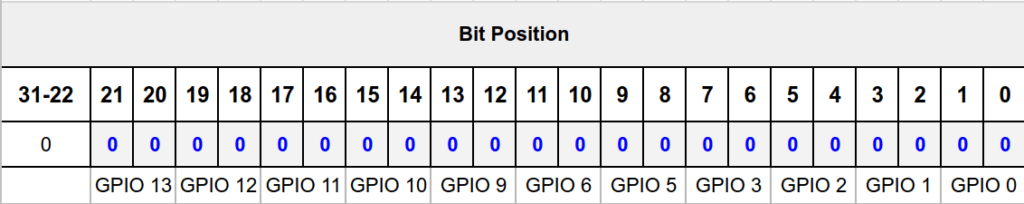
Now we have set 0 in all the required bit positions.
The Pinmux register value for setting all GPIO pins is 0000 0000 0000 0000 0000 0000 0000 0000 i.e 0x0 (hex).
Setting SPI2 in PinMux
To enable SPI 2 in the pinmux register, we have to enter 01 (binary) in the corresponding bit positions. Consider the following register diagram,
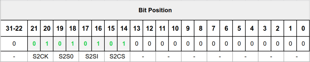
The hex equivalent of 0000 0000 0001 0101 0100 0000 0000 0000 is 0x154000. To enable SPI 2, the pinmux register should contain 0x15400.
Setting UART in PinMux
To enable UART 1 and UART 2 in the Pinmux register, we have to enter 01 (binary) in the corresponding bit positions.
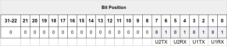
The hex equivalent of 0000 0000 0000 0000 0000 0000 0101 0101 is 0x55.
| Configuration | Pinmux register value |
|---|---|
| UART 1 | 0x05 |
| UART 2 | 0x50 |
| UART 1 and UART 2 | 0x55 |
Setting PWM in pinmux register
To enable PWMs in the pinmux register, we have to enter 10 (binary) in the corresponding bit positions. Consider the following register diagram,

Now we can enable the required PWM by enabling the corresponding bit positions. Consider the above figure, as we can see all the PWMs are enabled. The hex equivalent for that is 0000 0000 0000 0010 1010 1010 1000 0000 is 0x2AA80
| Configuration | Pinmux register value |
|---|---|
| Only PWM 0 | 0x80 |
| Only PWM 1 | 0x200 |
| Only PWM 2 | 0x800 |
| Only PWM 3 | 0x2000 |
| Only PWM 4 | 0x8000 |
| Only PWM 5 | 0x20000 |
| All PWMs | 0x2AA80 |
Akshaya currently works at the RISE labs. Her favorite subjects are Web designing and Microprocessors. She loves learning about new things and writing about them!