
Serial Peripheral Interface (SPI) is an interface bus commonly used to send data between microcontrollers and small peripherals such as shift registers, sensors, and SD cards. In the previous article, we saw how UART works. Whereas UART uses start and stop bits to check the validity of the data and a common baud rate between the devices to ensure correct transmission. SPI uses a synchronized clock signal to ensure proper transmission

Main Features:
- Synchronous
- Full-duplex
- Master/ Slave communication with a single Master
- Unlike UART and I2C where data is sent in packets, any number of bits can be sent and received as a continuous stream.

SPI Master: The device that generates clock signal is called the MASTER
SPI Slave: The device that takes instruction from the master. There can be multiple slaves.
SPI’s four Logic pins:
- SCLK: Serial Clock (Output from Master)
- MOSI: Master Out/ SLave in (Data output from Master)
- MISO: Master In/ Slave Out (Data output from Slave)
- SS: Slave Select
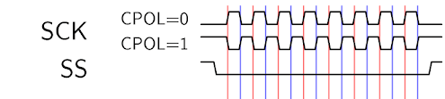
SCLK: Serial Clock
The serial clock is used to keep both sides in perfect sync. UART uses the baud rate to ensure proper transmission between two devices whereas here a common clock signal. A clock signal is an oscillating signal that tells the receiver exactly when to sample the bits on the Data line. This could be rising (low to high) or falling (high to low) edge. So when the receiver detects the edge, it samples (reads) the data from the data line. As the Clock is sent along with the Data, specifying speed is not important.
SS: Slave Select
In the case of multiple slaves, the master selects the slave with which the transmission occurs.

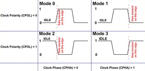
SPI Mode: Polarity and Clock Phase
The SPI interface defines no protocol for data exchange, limiting overhead and allowing for high speed data streaming. Clock polarity (CPOL) and clock phase (CPHA) can be specified as ‘0’ or ‘1’ to form four unique modes to provide flexibility in communication between master and slave.
| Mode | CPOL | CPHA |
|---|---|---|
| 0 | 0 | 0 |
| 1 | 0 | 1 |
| 2 | 1 | 0 |
| 3 | 1 | 1 |
The clock (SCLK) signal may be inverted (CPOL=1) or non-inverted (CPOL=0).
Different modes in SPI: If CPHA=0, the data are captured on the leading (first) clock edge, regardless of whether that clock edge is rising or falling. If CPHA=1, the data are captured on the trailing (second) clock edge;
Akshaya currently works at the RISE labs. Her favorite subjects are Web designing and Microprocessors. She loves learning about new things and writing about them!