A TFT display (Thin-Film Transistor display) refers to a type of flat-panel display technology that uses thin-film transistor technology to improve image quality and response time. A 1.44-inch TFT display indicates the screen size diagonally, which is quite small and commonly used in applications where space is limited or where a small visual output is sufficient. This 1.44-inch TFT display is compact, colourful, and bright. The pixels of the display can be configured and accessed using 4 – wire SPI communication Interface. The 1.44′′ screen contains 128 x 128 colour pixels. This display is a real TFT, in contrast to the low-cost “Nokia 6610” and comparable LCD displays, which are CSTN type and result in poor colour and slow refresh.
This TFT module is powered by the ILI9163C driver, a 262,144-color one-chip SoC driver for a-TFT liquid crystal display. This 1.44-inch TFT LCD Colour Screen Module SPI Interface has a resolution of 128 × 128 and 262 colours. The ILI9163C supports serial peripheral interfaces (SPI).
In this blog post, we delve into how to interface TFT display with Shakti.

Main features
| Display Technology | TFT (Thin-Film Transistor display) |
| Driver IC | ILI9163C |
| MCU Interface | SPI |
| Screen Size | 1.44″ |
| Resolution | 128×128 pixels |
| Operating Voltage | 5V |
| Logic IO port voltage | 3.3V(TTL) |
| LED backlight | 3.3V |
Protocol
Here, in this project, SPI protocol is used to interface with Shakti.
Step 1: What You Will Need
- Arty-A7 35T/100T board with either
pinaka, parashu or vajraprogrammed - 1.44 inch TFT LCD Color Screen Module.
- Micro USB Cable.
- Jumper Wires.
- shakti-sdk and shakti-tools installed and ready.
Step 2: The Circuit
| Display Pins | Purpose |
| VCC | Power to the display |
| GND | Ground connection for the display |
| CS | To select the display as the target device for SPI communication |
| RST | To reset the display |
| A0 | To indicate whether the data is a command or actual display data |
| SDA | Sending data from the microcontroller |
| SCK | Clock signal generated by the microcontroller |
| LED | Positive voltage to the backlight LED |
Connection of TFT display with Shakti
| Display Pins | Board Connection |
| VCC | 5V |
| GND | GND |
| CS | GPIO 10 |
| RST | GPIO 5 |
| A0 | GPIO 7 |
| SDA | GPIO 11 |
| SCK | GPIO 13 |
| LED | 3.3V |
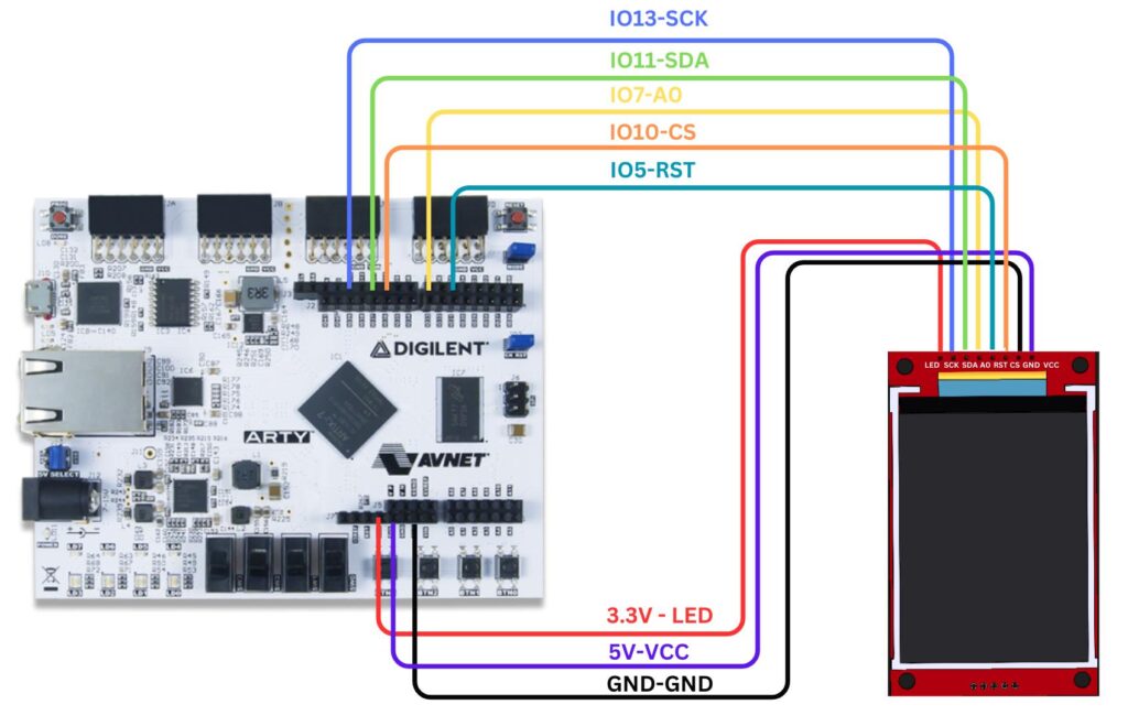
Here we use Arty100T for instance. Also, the connections are the same in Arty35T boards. For better clarity, check the device pin mapping for pinaka, parashu and vajra for better understanding.
Step 3: Code
Please click here to have a look at the code of 1.44 inch TFT LCD Color Screen Module
Code can be compiled and run using the following ways,
- Using terminal on a system with shakti-sdk and shakti-tools installed (Manual method).
Step 4.1: Manual Method
- Move to
shakti-sdk
cd shakti-sdk
- Compile using
make software PROGRAM=tft_display TARGET=vajra. Typemake list_applnsto list all the applications available in the SDK. Target can be eitherparashu, pinaka or vajra.
- For instance, Use target as
vajra
make software PROGRAM=tft_display TARGET=vajra
4.1.2 Execution:
Once the application is built, the executable is generated in the output folder. The executable is in ELF file format and they have the extension .shakti. Now, open three terminals, one for each of the following,
- One terminal for UART terminal display
(miniterm) - Another for
GDB server - And the last one for
OpenOCD.
Terminal 1: Firstly Connect to serial output by using miniterm or gtkterm with the baud rate of 19200.
For instance,
$ sudo miniterm /dev/ttyUSB1 19200
Note:
- “/dev/ttyUSB1” – ttyUSB means “USB serial port adapter”
- The “1” (“0” or “1” or “2”“here means the USB device number on your system. The FPGA board is connected to that USB device number.
Terminal 2: After that, Connect to the FPGA board by using the OpenOCD provided by shakti-tools and its respective configuration file. (Read how OpenOCD and RISC-V GDB work together to establish a connection between our PC and the Microprocessor)
$ cd shakti-sdk
$ cd ./bsp/third_party/vajra
$ sudo $(which openocd) -f ftdi.cfg
For pinaka and vajra, Go to cd ./bsp/third_party/<pinaka or vajra>
Terminal 3: Now, open either 32-bit or 64-bit RISC-V GDB based on your architecture i.e riscv64-unknown-elf-gdb or riscv32-unknown-elf-gdb respectively from shakti-tools.
The output executable is created in <path-to-shakti-sdk>/software/examples/i2c_applns/tft_display/output as tft_display.shakti. Load up the .shakti file by following the below steps,
$ riscv64-unknown-elf-gdb
(gdb) set remotetimeout unlimited
(gdb) target remote localhost:3333
(gdb) file path/to/executable
(gdb) load
(gdb) c
Output

Balaji is currently working in RISE Lab. He has a deep passion for tinkering with sensors and development boards..