
In this tutorial, the ESP8266 WiFi Module is used with a bmp280 sensor on the SHAKTI Processor. In the previous article, we saw how to use BMP280 with SHAKTI. Now we are going to use 2 two sensors – ESP8266 and BMP280 with SHAKTI. We are going to get the temperature and pressure values from the BMP280 sensor and send it to thingspeak.com over WiFi using ESP8266 WiFi module
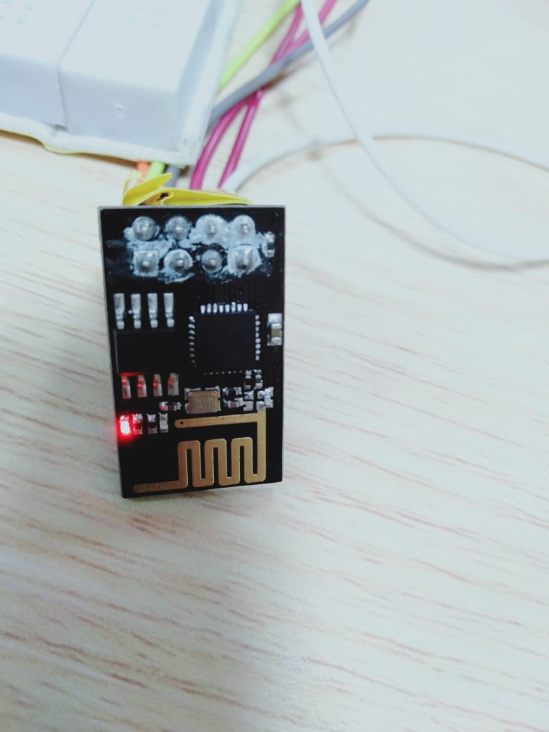
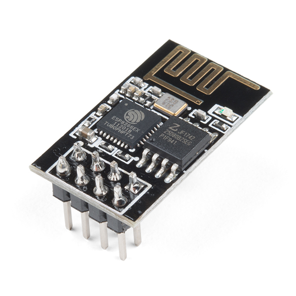
The ESP8266 WiFi Module is integrated with a TCP/IP protocol stack that can give any micro controller access to your WiFi network. The ESP8266 is capable of either hosting an application or offloading all WiFi networking functions from another application process. Each ESP8266 module comes pre-programmed with an AT command set firmware i.e you can simply hook this up to your development board and get about as much WiFi-ability as a WiFi Shield offers.
Protocol:
The ESP8266 WiFi Module works with SPI, I2C and UART protocol. In this tutorial ESP8266 WiFi Module is used with UART to communicate with SHAKTI. BMP280 is used with I2C protocol.
Video Tutorial:
Step 1: Requirements
- Arty7 35t/100T board with either
pinaka, parashu or vajraprogrammed on it. - shakti-sdk and shakti-tools installed or Platform IO installed and ready
- ESP8266 WiFi Module and BMP280
- Micro USB Cable and Jumper Wires.
- A Hotspot or WiFi for Internet connectivity.
- A channel in thingspeak.com to receive data from ESP8266.
- API key from the configured
thingspeakchannel.
Note: shakti-sdk and shakti-tools are currently a private repository. Please login or sign up to Gitlab and request access here before using it.
Step 2: The Circuit
Firstly, let’s see the ESP8266 connections only.
- GND connected with GND.
- TX (GPIO-1) connects with GPIO-0.
- CH_EN connects with 3.3V.
- RX connects with GPIO-1.
- VCC connects with 3.3V(only).
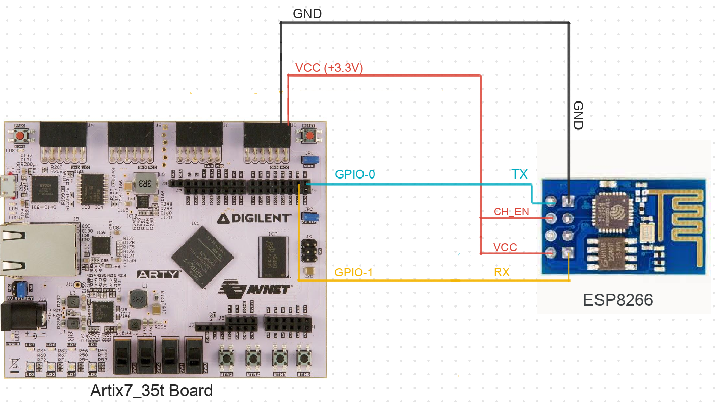
Note: GPIO-0 and GPIO-1 are UART pins. Here we use Arty35t for instance. Also, the connections are the same in Arty100t boards. For better clarity, Check the device pin mapping for pinaka, parashu and vajra.
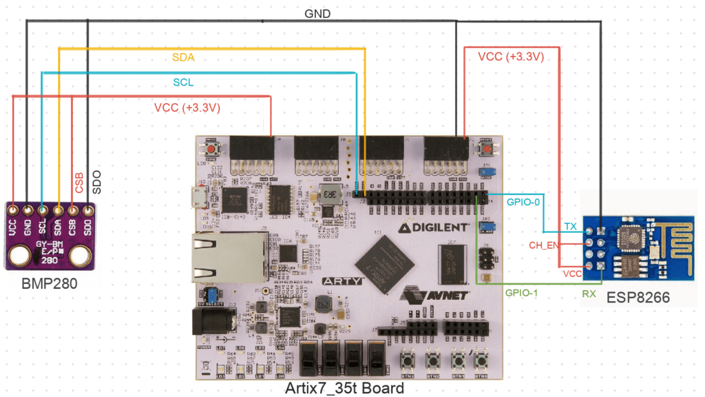
Now when we connect both ESP8266 and BMP280 to the board,
The connections for BMP280 is as follows,
- VCC to 3.3V
- GND to GND
- SCL to SCL of board
- SDA to SDA of board
- CSB to 3.3V
- SDO to GND
Step 3: Code
Please click here to have a look at the code. We send the temperature and pressure reading from BMP280 to the thingspeak server via the ESP8266 WiFi module. The ESP8266 WiFi module uses 115200 as the baud rate to communicate with the thingspeak server.
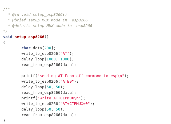
Setup ESP8266:
Every wireless, as well as the dial-up modems, require an AT command to interact with a computer machine.
Therefore AT commands are used here for the communication between the WiFi module and the thingspeak server. Also, AT stands for attention.
The following AT commands are required to connect, to set up and to send the data to the server. Please check the source code, where all the commands are used for device set up and configuration.
Steps to connect to WiFi:
- AT+RST
- AT+CWMODE=1
- AT+CWLAP
- AT+CWJAP=\”WiFi or Hotspot name\”,\”Password of the WiFi\””
- AT+CIFSR
- ATE0
- AT+CIPMUX=0
Steps to send data to the server:
- AT+CIPSTART=\”TCP\”,\”Server_name or api link\”,Port_No.
- AT+CIPSEND=Number of bits want to send
- GET “Send the value to the server through API keys”
- AT+CLOSE
Code can be compiled and run using the following ways,
- using terminal and a system with shakti-sdk and shakti-tools installed.
- using Platform IO IDE
Step 4.1: Manual Method
4.1.1 Compile and build
- Move to
shakti-sdk
cd shakti-sdk
- Compile using
make software PROGRAM=? TARGET=?. However, typemake list_applnsto list all the applications available in the SDK. Target can be eitherparashu, pinaka or vajra.
For instance, use the target as parashu,
make project PROGRAM=weatherstation_bmp280 TARGET=parashu
4.1.2 Execution:
Once the application is built, the executable is generated in the output folder. The executable is in ELF file format and they have the extension .shakti. Now, open three terminals, one for each of the following,
- One terminal for UART terminal display
(miniterm) - Another for
OpenOCD. - And the last one for
GDB server.
Terminal 1 (Optional):
Firstly, Connect to serial output by using miniterm or gtkterm with the baud rate of 19200.
As the main aim of this project is to send the values we get from BMP280 to the thingspeak server via ESP8266. The serial terminal output is not required since it’s only for our easy understanding.
For instance,
$ sudo miniterm.py /dev/ttyUSB1 19200
Note:
- “/dev/ttyUSB1” – ttyUSB means “USB serial port adapter”
- The “1” (“0” or “1” or “2”“here means the USB device number on your system. The FPGA board is connected to that USB device number.
Terminal 2: After that, Connect to the FPGA board by using the OpenOCD provided by shakti-tools and its respective configuration file. (Read how OpenOCD and RISC-V GDB work together to establish a connection between our PC and the Microprocessor)
For instance, if we use parashu,
$ cd shakti-sdk
$ cd ./bsp/third_party/parashu
$ sudo $(which openocd) -f ftdi.cfg
For pinaka and vajra, Goto cd ./bsp/third_party/<pinaka or vajra>
Terminal 3: Now, open either 32bit or 64bit RISC-V GDB based on your architecture i.e riscv32-unknown-elf-gdb or riscv64-unknown-elf-gdb respectively from shakti-tools.
The output executable is created in <path-to-shakti-sdk>/software/projects/weatherstation_bmp280/output as weatherstation_bmp280.shakti.
Now load up the .shakti file by following the below steps. For Parashu,
$ riscv32-unknown-elf-gdb
(gdb) set remotetimeout unlimited
(gdb) target remote localhost:3333
(gdb) file path/to/executable
(gdb) load
(gdb) c
4.1.3 Upload to flash
The SHAKTI-SDK has an uploader tool that is used to load content (such as ELF) to flash, after building the image.
- Goto the right directory.
cd shakti-sdk
- Use
make uploadcommand to build and upload the application to the flash automatically.
make upload PROGRAM = weatherstation_bmp280 TARGET = parashu
Here, the bare metal user application created is "PROGRAM". The target can be either parashu, pinaka or vajra. Type make list_applns to list all the applications available in the SDK.
Step 4.2: Using Platform IO
We can use IDE’s like Platform IO to compile, build, run, upload and debug. Please read the article on Platform IO on SHAKTI to understand the steps.
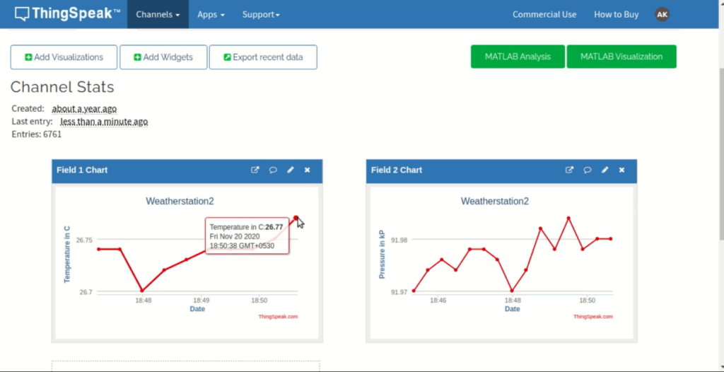
Output (thingspeak)
Open thingspeak website to view the temperature and pressure data transmitted over WiFi using ESP8266 module to thingspeak server.
Akshaya currently works at the RISE labs. Her favorite subjects are Web designing and Microprocessors. She loves learning about new things and writing about them!


Hi Akshaya,
Could you specify where details about *pinmux_config_reg can be found. Setting it to 0x5 enable UART1. What for Both UART1 and UART2?
thanks
Hi Ajit, 0x55 would enable both UART1 and UART2. I ll try to get a short article on pinmux.
Hi Akshaya,
Thanks for the reply. I am unable to get any signal from Tx pins of UART1 and UART2 (CK_IO[1], CK_IO[3] Pins Header J4 pin 2 and 4) when using write_uart_character() function. Could you point out possible problems.
thanks
Ajit
Hi Ajit,
Assuming you have vajra programmed, Make sure your connections are right. Also for checking, you can connect your UART1 TX [IO1] to UART1 [IO0] RX pin and try printing the values.
Hi,
My question is in context of Vajra processor on Arty A7 100T board
please provide following clarifications:
1) The number of UART ports in Vajra processor – Is it 1 or 3.
2) If more than 1 then they are mapped to which pins?
For this project to work GPIO0 and GPIO1 should be mapped to UART on Vajra as well.
thanks
Ajit
Hi ajit, Vajra has 3 UARTs. checkout the Pin mapping. https://shakti.org.in/docs/shakti-soc-user-manual.pdf