
Pulse Width Modulation(PWM) is a current control technique that is used in many applications such as dimming of LEDs, controlling the speed of motors in a very efficient way.
PWM is basically a square wave with ON and OFF signals.
Some of the existing applications include,
- Determining the direction in servo motors
- Inverter Air conditioners
- Inverter refrigerators,
- variable fan speed controllers
PWM has changed the world with the reduction in power consumption it produced. For instance, the inverter ac uses only half the power an usual ac would use.
How PWM works?
Pulse Width Modulation (PWM) works by pulsating the DC Current and varying the amount of time it stays on. This “On Time” is called Duty cycle.
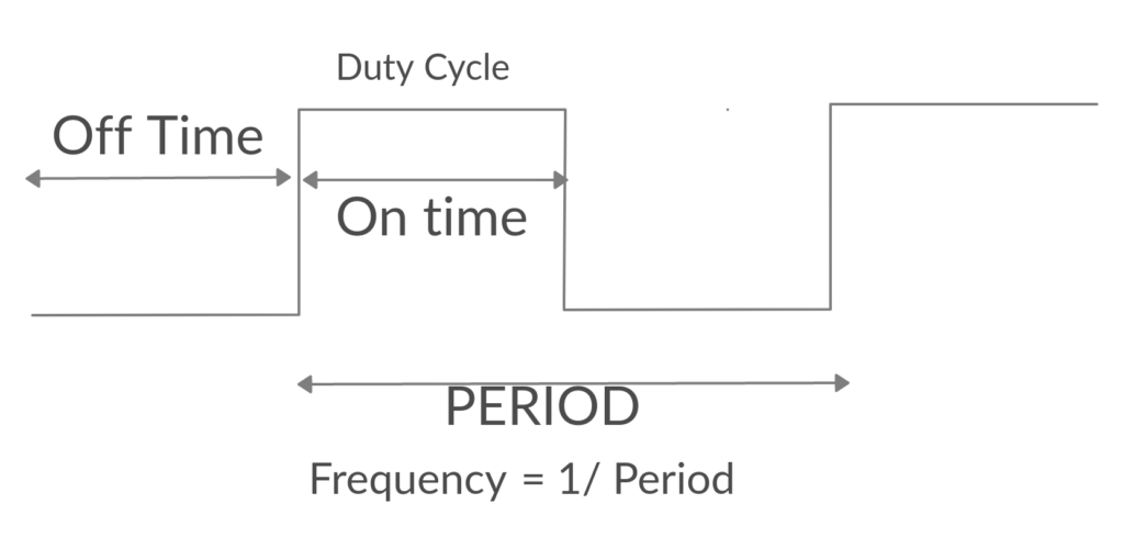
By altering the duty cycle, we can control the appliances. For instance if the duty cycle is set at 70%, the electric pulse is ON for 70% of the time and Off for the rest 30%. This way, they only consume as much power as they need, but without the usual consequence of burning off unused current as heat.

Period = 1/ Frequency
Period = Ton + Toff
ON (HIGH) of PWM DUTY = PWM Period / (Duty + 1) .
The duty cycle and the period of the pulse can be varied through DUTY and PERIOD registers respectively.
We are going to use a simple led blink program to demonstrate.
Step 1: Requirements
- Arty7 35t/100t board with either
pinaka, parashu or vajraprogrammed. - shakti-sdk and shakti-tools installed or Platform IO installed and ready
- One LED.
- Resistors (to protect LED).
- Micro USB Cable.
- Jumper Wires.
Note: shakti-sdk and shakti-tools are currently a private repository. Please login or sign up to Gitlab and request access here before using it.
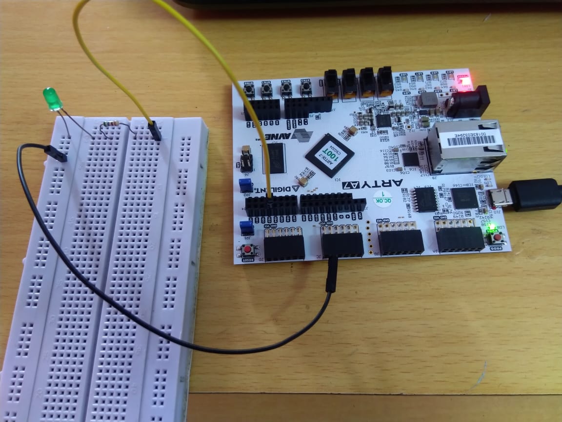
Step 2: The Circuit
The PWM pins are masked with GPIO pins respectively,
- Cathode to ground
- PWM0 to GPIO3
- PWM1 to GPIO5
- PWM2 to GPIO6
- PWM3 to GPIO9
- PWM4 to GPIO10
- PWM5 to GPIO11
The pin connection,
- LED +ve (Long Leg) to GPIO3 [IO3] i.e PWM0
- LED -ve (Short Leg) to GND
Step 3: Code
Please click here and have a look at the code. Using PWM, the LED light blinks at the specified frequency.
Code can be compiled and run using the following ways,
- using terminal and a system with shakti-sdk and shakti-tools installed.
- using Platform IO IDE
Step 4.1: Manual Method
4.1.1 Compile and build
- Move to
shakti-sdk
cd shakti-sdk
- Compile using
make software PROGRAM=? TARGET=?. Typemake list_applnsto list all the applications available in the SDK. Target can be eitherparashu, pinaka or vajra.
For instance, Use target as vajra
make software PROGRAM=pwmled TARGET=vajra
4.1.2 Execution:
Once the application is built, the executable is generated in the output folder. The executable is in ELF file format and they have the extension .shakti. Now, open three terminals, one for each of the following,
- One terminal for UART terminal display
(miniterm) - Another for
OpenOCD. - And the last one for
GDB server.
Terminal 1: Firstly, Connect to serial output by using miniterm or gtkterm with the baud rate of 19200.
For instance,
$ sudo miniterm.py /dev/ttyUSB1 19200
Note:
- “/dev/ttyUSB1” – ttyUSB means “USB serial port adapter”
- The “1” (“0” or “1” or “2”“here means the USB device number on your system. The FPGA board is connected to that USB device number.
Terminal 2: After that, Connect to the FPGA board by using the OpenOCD provided by shakti-tools and its respective configuration file. (Read how OpenOCD and RISC-V GDB work together to establish a connection between our PC and the Microprocessor)
For instance, if we use vajra,
$ cd shakti-sdk
$ cd ./bsp/third_party/vajra
$ sudo $(which openocd) -f ftdi.cfg
For pinaka and parashu, Goto cd ./bsp/third_party/<parashu or vajra>
Terminal 3: Now, open either 32bit or 64bit RISC-V GDB based on your architecture i.e riscv32-unknown-elf-gdb or riscv64-unknown-elf-gdb respectively from shakti-tools.
The output executable is created in <path-to-shakti-sdk>/software/examples/pwm_applns/pwmled/output as pwmled.shakti.
Load up the .shakti file by following the below steps. For Vajra,
$ riscv64-unknown-elf-gdb
(gdb) set remotetimeout unlimited
(gdb) target remote localhost:3333
(gdb) file path/to/executable
(gdb) load
(gdb) c
4.1.3 Upload to flash
Steps to generate standalone user application:
The SHAKTI-SDK has a uploader tool that is used to load a content (such as ELF) to flash, after building the image.
- Goto the right directory.
cd shakti-sdk
- The make upload command is used to build and upload the application to the flash automatically.
make upload PROGRAM = pwmled TARGET = vajra
PROGRAM is the new bare metal user application that is created. Target can be either parashu, pinaka or vajra. Type make list_applns to list all the applications available in the SDK.
Step 4.2: Using Platform IO
We can use IDE’s like Platform IO to compile, build, run, upload and debug. Please read the article on Platform IO on SHAKTI to understand the steps.
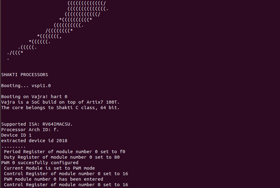
Miniterm Output
LED Blink:
Akshaya currently works at the RISE labs. Her favorite subjects are Web designing and Microprocessors. She loves learning about new things and writing about them!